
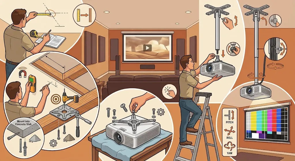
Transforming a living room or spare bedroom into a true home theatre is one of the most rewarding DIY projects you can tackle. While setting a projector on a coffee table works in a pinch, hanging it overhead unlocks the clean look, fixed focus, and immersive atmosphere of a real cinema. Mounting a projector to the ceiling might seem intimidating if you have never drilled into joists or calculated throw ratios, but the process is straightforward when broken down logically.
With a few basic tools, careful measurements, and a free afternoon, you can securely mount your display device and achieve a perfectly squared, razor sharp picture.
1. Before You Begin: Preparing for a Flawless Installation
A smooth installation relies on preparation. Before picking up a drill, gather your tools, examine your room’s anatomy, and ensure you have hardware tailored to your specific setup.
Essential Tools and Hardware You'll Need
Having your gear laid out beforehand prevents frustrating mid project trips to the hardware store. You will need:
-
A stud finder (preferably one with deep scan and AC wire detection)
-
A tape measure and a long bubble level
-
An electric drill with wood or masonry drill bits
-
A socket wrench set or a sturdy screwdriver set
-
A pencil for precise marking
-
Painter's tape to mark boundaries without harming paint
-
A sturdy step ladder
-
Zip ties or cable management raceways
Evaluating Your Ceiling Type and Structural Support
Projectors and their mounting hardware carry real weight, and fan vibration or accidental bumps can loosen weak anchors over time. You must identify what lies above your ceiling drywall.
Standard homes feature wooden ceiling joists spaced either 16 or 24 inches apart on centre. If you are working in a basement, you might encounter steel studs or direct concrete slabs. Suspended or drop ceilings present another challenge entirely. Never anchor a projector into plain drywall with hollow wall anchors; ceiling drywall is designed to hold its own weight, not an active, vibrating overhead load. You need to anchor directly into a solid structural framing member or concrete base.
Choosing the Right Projector Ceiling Mount
Mounts generally fall into three categories: flush mounts, telescoping pole mounts, and structural truss mounts.
-
Flush mounts hold the unit just a few inches below the ceiling. They are ideal for rooms with low ceilings (eight feet or under) and projectors with generous vertical lens shift.
-
Telescoping mounts drop the unit down on an adjustable pole, making them perfect for vaulted or high ceilings where the image needs to descend closer to eye level.
Look for a mount rated for at least double the weight of your projector, featuring a universal "spider arm" configuration and independent adjustments for pitch, roll, and yaw.
2. Step 1: Calculate the Exact Placement and Throw Distance
Before driving a single screw, you must calculate exactly where the projector needs to hang relative to your screen. Guesswork here leads to blurry images, unwanted digital distortion, or an off centre picture.
|
Placement Element |
Position |
|
Ceiling Mount Location |
Above the projector |
|
Throw Distance |
Between the projector lens and screen |
|
Light Path |
From projector to screen |
|
Screen Area |
Final projected image area |
Determining Your Projector's Throw Distance
Every projector lens projects light outward in a cone shape defined by its throw ratio. This ratio tells you how wide the image will be relative to how far the lens sits from the screen. The maths is simple:
Throw Distance = Screen Width × Throw Ratio
If your target screen is 100 inches wide (measured horizontally, not diagonally) and your projector has a throw ratio of 1.5:1, the front of the lens must sit precisely 150 inches (12.5 feet) away from the screen surface.
If your projector features a zoom lens, for instance, a range of 1.4:1 to 1.8:1, you have an installation window. Calculate both the minimum and maximum distances, then aim for the middle of that range. Operating near the centre of the zoom lens leaves extra flexibility for physical fine tuning later.
Calculating Vertical Offset and Lens Shift
Projectors rarely throw light in a straight horizontal line. Most project light upward at an angle when sitting flat, or downward when inverted overhead. This vertical drop is known as the offset.
Consult your projector's manual to find its default offset percentage. An offset of 10% means that for a 50 inch tall screen, the centre of the lens needs to sit 5 inches above the top edge of the screen frame when the ceiling is mounted upside down.
If your unit includes optical lens shift, you have more leeway. Physical knobs or dials move the lens elements internally, shifting the image up, down, left, or right without tilting the projector. If your device lacks optical lens shift, your height calculation must be spot on down to the fraction of an inch.
Marking the Centre Point on Your Ceiling
To keep the image square, the centre of the projector’s lens, not the centre of its chassis, must align with the exact horizontal centre of your screen.
-
Measure the width of your screen surface, divide by two, and make a small mark at the top centre of your screen frame.
-
Run a piece of painter's tape out onto the ceiling along this centre axis, using a laser level or string line stretched perpendicular to the screen wall.
-
Measure along this line from the screen back toward the room until you reach your calculated throw distance.
-
Mark this point on the painter's tape. This mark represents where the front glass of the projector lens needs to sit when fully hung.
3. Step 2: Install the Ceiling Bracket
Now that you have pinpointed the lens location, you can secure the primary mounting plate to the ceiling structure overhead.
|
Ceiling Mount Component |
Position |
|
Ceiling Joist |
Structural support above |
|
Pilot Holes |
Drilled into the joist |
|
Mounting Plate |
Fixed against the ceiling |
|
Heavy Duty Lag Screws |
Secure the plate to the joist |
Locating Ceiling Joists for Maximum Stability
Use a quality stud finder along your marked centre axis line to locate the wooden ceiling joists. Run the stud finder across the ceiling perpendicular to the direction the joists run.
Once you get a stud signal, mark both the left and right edges of the joist, then find the centre point between those edges. Verify the centre point by sliding a thin finishing nail into the drywall on either side. You should feel solid resistance in the centre, but hollow space when piercing outside the edges.
If your ideal throw distance falls in the empty space between two parallel joists, do not compromise by hanging the mount from drywall anchors. Instead, crawl into the attic or open the ceiling space to install a wooden 2 × 4 bridge block spanned securely between the two joists. Alternatively, securely fasten a decorative wood mounting block to the underside of two joists, spanning the gap, and anchor your plate to that block.
Drilling Pilot Holes and Securing the Mount Plate
Once you have identified solid wood framing directly above or near your marked throw point:
-
Hold the ceiling mounting plate against the ceiling, aligning its centre hole with your target mark.
-
Use a bubble level to ensure the plate rests parallel to the screen wall.
-
Mark the mounting bolt holes onto the ceiling using a pencil.
-
Drill pilot holes into the joist structure using a drill bit slightly smaller than the core of your lag bolts (typically a 3/16 inch bit for standard 1/4 inch heavy lag screws). Drilling pilot holes prevents the dense joist wood from splitting under pressure.
-
Drive heavy duty lag bolts through the plate washers and into the ceiling joist using a socket wrench. Tighten until the plate sits flush and firm against the ceiling without over torquing.
Mounting Bracket Options for Drywall or Concrete
If you are mounting into a solid concrete slab or brick ceiling, the process differs slightly:
-
Use a masonry bit to drill holes matching the diameter of heavy duty steel expansion anchors or masonry lag shields.
-
Vacuum out concrete dust from the hole so the anchor can seat fully.
-
Tap the concrete anchors flush with the ceiling surface using a mallet.
-
Secure the plate with structural machine bolts tightened into the expanding anchors.
Never rely on plastic expansion plugs or toggle bolts in plain drywall ceiling applications for high value A/V equipment.
4. Step 3: Attach the Plate and Arms to the Projector
With the ceiling bracket secured, you can prepare the projector body itself. Mounting hardware attaches to threaded metal screw holes located on the bottom panel of the unit.
|
Projector Component |
Position |
|
Threaded Holes |
On the bottom of the projector |
|
Spider Arms |
Extend towards mounting holes |
|
Mounting Interface |
Positioned at the centre |
|
Mounting Screws |
Secure the arms to the projector |
Inverting the Projector Safely
Clear a wide, clean workspace on a soft surface, like a dining table covered with a thick microfiber towel or blanket. Gently place the projector upside down on the towel. Upside down mounting is required because ceilings position the lens higher than the image frame, requiring the downward projection angle native to inverted operation.
Remove any decorative screw covers covering the mounting holes on the underside of the chassis.
Aligning and Securing Universal Spider Arms
Universal projector mounts feature dynamic metal extension arms, often called spider arms, that pivot and slide to match varying hole patterns.
-
Locate the correct mounting screws for your projector thread depth. Mount kits supply various metric hardware packs (typically M4, M5, or M6 screws). Thread them in by hand first to test the depth and thread pitch; never force a screw.
-
Loose fit the spider arms to the central mounting interface plate.
-
Swivel and extend the arms so their slotted feet align over the threaded mounting points on the projector's belly.
-
Insert the correct machine screws along with lock washers or rubber spacers provided by the mount manufacturer.
Balancing the Weight Distribution
Before fully tightening down the assembly, locate the approximate centre of gravity of your projector. For many units, this sits slightly away from the geometric centre due to the weight of optical glass assemblies housed on one side.
Position the central hub plate directly over this point of balance. Aligning the plate with the centre of gravity stops the projector from pitching forward or rolling to one side under its own weight after hanging, making precision adjustment much easier. Once aligned, tighten down every bolt on the spider arm joints securely.
5. Step 4: Hang and Secure the Projector
This stage brings everything together. Having a second pair of hands for safety during this step is strongly recommended.
|
Mount Component |
Position |
|
Ceiling Joist |
Structural support |
|
Ceiling Plate |
Attached to joist |
|
Extension Pole or Drop Rod |
Connects plate to mount |
|
Hinge |
Provides adjustment |
|
Projector |
Secured below |
Connecting the Extension Pole and Mount Mechanism
If your room setup requires an extension pole to clear low hanging light fixtures or drop down from high ceilings, thread the extension pole into the secured ceiling plate now. Feed your power and video cables down through the centre of the hollow pole before attaching hardware to the lower end. This hides unsightly wire runs inside the structural tubing.
If you are flush mounting, assemble the dynamic ball joint or hinge connector directly between the ceiling plate and the projector adapter plate.
Locking the Assembly into Place Safely
-
Carefully lift the projector using both hands under the body structure, never hold it by the lens assembly.
-
Climb your stepladder while your helper holds the weight, or pass the unit up to a secure position.
-
Hook or slide the projector’s adapter plate into the receiver mechanism on the ceiling mount. Most modern mounts use a "hook and hang" system where an alignment pin catches safety channels automatically.
-
Immediately insert and hand tighten the main safety retaining bolt or lock pin specified by the manufacturer.
-
Verify that the quick release lock is engaged before releasing your grip on the projector body.
Managing Cables for a Clean Finish
Loose, dangling cords spoil the look of an overhead installation. Route your power cord and long High Speed HDMI cables (preferably active optical HDMI cables for runs exceeding 25 feet) along the mount structure.
-
Leave a small loop of slack directly behind the projector ports. This "drip loop" prevents tension on delicate HDMI ports when you adjust the tilt angle.
-
Use hook and loop straps or zip ties to bundle cables neatly against the drop pole.
-
If running cables across drywall, run paintable surface raceways along the ceiling and down wall corners to match your trim colour.
6. Step 5: Fine Tune Your Picture and Calibration
With the unit hanging safely, it is time to turn on the equipment, feed an image signal, and dial in geometric precision.
|
Adjustment |
Movement |
|
Yaw |
Rotates left or right |
|
Roll |
Tilts left or right |
|
Pitch |
Tilts up or down |
Adjusting Pitch, Roll, and Yaw
Power on your projector and select its factory test grid pattern. Navigate your projector's settings menu to flip the image orientation to "Rear Ceiling" or "Front Ceiling" mode so your image displays right side up.
Loosen the lock screws on your mount's alignment joint slightly to make fine mechanical adjustments along three axes:
-
Yaw (Horizontal Rotation): Swivel the projector left or right so the light cone hits the screen dead on at 90 degrees. If the left side of the image looks taller than the right side, your yaw needs adjusting.
-
Pitch (Vertical Tilt): Tilt the projector nose up or down to align the top and bottom borders of the image with your screen edge.
-
Roll (Side to Side Tilt): Rotate the body clockwise or counterclockwise until the top edge of the projected image runs level with your screen horizon.
Always physically adjust the mount before relying on software controls. Getting the physical placement correct preserves every drop of resolution and brightness.
Optimising Focus and Zoom Settings
Adjust the physical zoom ring or electronic zoom motor until the projected pattern fills your screen frame. Next, focus the image carefully.
To get razor sharp focus:
-
Walk up to the screen surface.
-
Look closely at text or screen pixel structures in the central third of the screen.
-
Adjust the focus mechanism slowly back and forth, stopping at the sharpest pixel boundary.
-
Check all four corners. If the centre is sharp but one corner remains soft, your projector is mounted slightly off axis and needs minor mechanical yaw or roll adjustments to fix lens tilt.
Minimising Digital Keystone Correction
Digital keystone correction squeezes an image via internal processing to fix trapezoidal distortion caused by poor placement angles. Avoid relying heavily on this feature.
|
Keystone Distortion |
Correct Physical Alignment |
|
Costs Pixel Resolution |
Preserves Full Quality |
Digital keystone scales pixels artificially, which reduces image sharpness, introduces input lag (a problem for gaming), and decreases screen brightness. Use mechanical lens shift, physical height adjustments, and bracket levelling to square the picture frame. Use digital keystone only as a last resort for fractional fixes.
7. Common Troubleshooting and Maintenance Tips
Even carefully executed installations run into minor issues over time. Use this quick reference guide to keep your ceiling mounted setup performing at its best:
|
Issue |
Root Cause |
Solution |
|
Trapezoidal Picture Shape |
Lens sits unlevel or off axis relative to the screen surface. |
Recheck pitch and yaw angles on the mount hardware; avoid jumping straight to digital keystone corrections. |
|
Image Drifts / Sags Over Time |
Mount lock screws are under tightened or weight is unbalanced. |
Recentre the spider hub arms over the projector’s centre of gravity and tighten lock nuts down fully with a socket wrench. |
|
Image Shakes when Walking Overhead |
Ceiling joists flex from foot traffic, or mount is anchored into thin drywall. |
Reanchor the ceiling plate directly into solid structural joists or install a bridging cross brace between framing studs. |
|
Overheating or Loud Fan Noise |
Dust builds up inside airflow pathways or ceiling heat pockets. |
Ensure at least 12 inches of open air clearance on all sides of projector exhaust vents. Clean dust filters every 3 to 6 months. |
|
No Video Signal (Black Screen) |
Cable length degradation or strained, unseated HDMI connectors. |
Verify cable connection slack loops. For long cable runs (25+ feet), swap out copper HDMI lines for Active Optical Cables (AOC). |
Installing your own ceiling mount takes patience and careful measurement, but the payoff is clear: a rock solid, clutter free setup that turns movie night into a true cinema experience. Double check your calculations, anchor securely into solid structural framing, and take your time fine tuning the geometry. You will enjoy a bright, perfectly squared picture for years to come.
Share:
TV Wall Mount Weight Limit: How Much Weight Can It Hold?